Open Systems Interconnection (OSI) model is a reference model developed by ISO (International Organization for Standardization) in 1984, as a conceptual framework of standards for communication in the network across different equipment and applications by different merchants. It is now considered the primary architectural model for inter-computing and inter-networking communications. There are seven layers within the OSI model that serve to differentiate the various hardware and software functions that a network provides. Each layer depends on the proper functioning of the layer immediately below it to provide its raw functionality, which is enhanced and then passed to the next higher layer. Status messages may be communicated up or down the various layers, although each layer only communicates with its immediate neighbors. As each layer is solely dependent on the layer below it for lower-level services, higher layers are shielded from system, hardware, and software implementation details. This leads to the independence from specific systems and interoperability with many vendors’ offerings.
The Open Systems Interconnection (OSI) model is very useful for developing and understanding a big picture views of network processes because it provides this independence. However, the model doesn’t claim to exactly match any specific network technology. Each layer must encapsulate the data it receives into a standard format for the next higher layer, thus incurring an overhead, and in the name of efficiency, the lines between one or more layers can be blurred. Some layers may not specifically have counterparts in an actual network implementation. However, as a tool for understanding the considerations involved in networking, the OSI model is unparalleled.
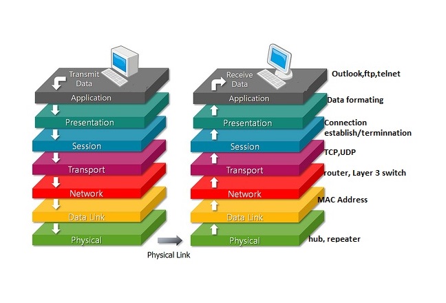
The Open Systems Interconnection (OSI) model’s seven layers, from the physical hardware level up to the actual network application that users interact with are as follows: the physical layer, the data-link layer, the network layer, the transport layer, the session layer, the presentation layer, and the application layer.
1. APPLICATION LAYER
Provides a means for the user to access information on the network through an application. This layer is main interface for the user to communicate with the application and the network. The application layer really close to the user, which means that both OSI application layer and communicating component. Therefore, if application programs fall outside is the scope of Open Systems Interconnection (OSI) model program. Application layer is functions typically that is identifying communication partners, determining resources availability, and synchronizing communication. Beside that, not only identifying communication partners but the application layer will determines the identity and availability its also will synchronizing communication partners for an application with data to transmit. When determining resources availability, the application layer must decide the sufficient network resources for the request communication, all communication between applications requires cooperation that is managed by application layer. Some examples of application layer implementations include Telnet, File Transfer Protocol(FTP), and Simple Mail Transfer Protocol(SMTP).
2. PRESENTATION LAYER
The presentation layer is the information that in an ordered and meaningful manner. The presentation layer functions are the syntax and semantics of the data transmission. Its converts local host computer data representations into a standard network format to transmit the network. The receiving side changed the network format into appropriate host computer format that the data can be utilized independently. The presentation layers also provide a variety of coding and conversion functions that are applied to application layer data. The function will ensure that the information sent from the application layer of the system would be readable by the application layer to another system. Examples of presentation layer are coding and conversion schemes include common data representation formats, conversion of character representation formats, common data compression schemes, and common data encryption schemes. In addition, common data representation formats or the use of standard image, sound, and videos formats, this is because enable the interchange of application data between the different types of computer systems. That is also helped us using different text and data representations such as EBCDIC and ASCII, uses conversion schemes to exchange information with systems. Standard data compression schemes enable data to compressed. Presentation layers also implement not typically associated with a particular protocol stack. It is standards for video included QuickTime and Motion Picture Experts Group(MPEG). QuickTime is an Apple computer specification for videos and audio, and MPEG is a standard program for video compression and coding.
3. SESSION LAYER
The usage of session layer is coordinates dialogue/session/connection between devices over the network. This layer manages communications between connected sessions. Examples of this layer are token management and network time synchronization. Beside that, the session layer establishes, manages and terminates communication sessions. The communication sessions consist of service requests and service responses that occurs between application located in different network devices. Furthermore, the requests and response are coordinated by protocols implemented at the session layer. There are some examples for session layer that is Zone Information Protocol(ZIP), the Apple Talk Protocol that coordinates the name binding process and Session Control Protocol(SCP).
4. TRANSPORT LAYER
The transport layer function as responsible for reliable transmission of data and service specification between hosts. The major function is responsibility of this layer is data integrity that the data can transmitted between hosts is reliable and timely. The upper layer data grams are broken down into network sized data grams if needed and then implemented using appropriate transmission control. The transport layer creates one or more than one network connection, its depending to condition. This layer also handles what type of connection will be created. Two important transport protocols are TCP (Transmission Control Protocol) and UDF (User Data Gram Protocol). These usage of transport layers are ensures reliable service, breaks the message into smaller packets, assign sequence number and sends them reliable transport connections are built on top of X.25 or IP.
5. NETWORK LAYER
The network layer responsible for the routing of data through the network, handles the addressing and delivery of data. This network layer provides for congesting control, accounting information for the network, routing, addressing, and several other functions.Internet Protocol is a good example of a network layer protocol. This layer does not deal with lost messages. The important of network layer protocols are concerned with the transmission of packets, choose the best path to send a packet, the routing may be complex in a large network example is internet and routing packets through a network maybe accomplished by using simple static routers or by using complex dynamic routing algorithms.
6. DATA LINK LAYER
Data link layer provides for the reliable delivery of data across a physical network. Furthermore, this layer commit with issues such as flow regulation, error detection and control and frames. This data link layer has the important task of creating and managing what frames are sent out on the network. In addition, the network data frame or packet is made up of check-sum, source address, destination address, and the data itself. The largest packet size that can be sent defines the Maximum Transmission Unit (MTU). Furthermore, (LAC) Logical Access Control is defines how data transferred over the cable and provides data link service to the higher layers. Not only that but (MAC) Medium Access Control defines who can use the network when multiple computers are trying to access it simultaneously. The data link layer also provides reliable transit of data across a physical network link. Different data link layer specifications define different network and protocol characteristics that including physical addressing, network topology, error notification, sequencing of frames, and flow control. The function of physical addressing is define how devices are addressed at the data link layers. Beside that,network topology consists of the data link specifications that often define how device are to be physically connected, such as bus or ring topology. Before that, error notification alerts upper-layer protocols that a transmission error has occurred, and the sequencing of data frames reorders frames that are transmitted out of sequence. Finally, flow control moderates the transmission of data so that the receiving device with more traffic than it can handle at one time.
7. PHYSICAL LAYER
Finally the physical layer view to handles the bit-level electrical or light communication across the networks channel. The physical layer defines the electrical, mechanical, procedural, and functional specifications for activating, maintaining, and deactivating the physical link between communicating network systems. For more details the physical layer specification define characteristics such as media, voltage levels, timing of voltage changes, physical data rates, maximum transmission distances and physical connectors. This layer ensures that a bit sent on one side of the network is received correctly on the other side. Physical layer is concerned with the following physical interface characteristic like electrical, and mechanical specifications, number of bits of second to be transmitted and transmission type like duplex or half-duplex.